Powerline
The team at Impulsions have many miles of experience in processing LiDAR for powerline utility sector. We have processed data for several customers to their specification with highest quality.
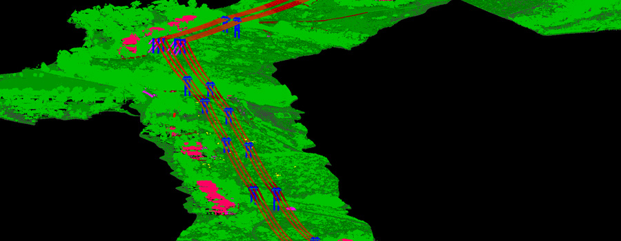
We have processes both transmission and distribution powerline projects from ALS, MLS and LiDAR acquired via drones. A typical project scope of powerline project that we have processed the LiDAR to is:
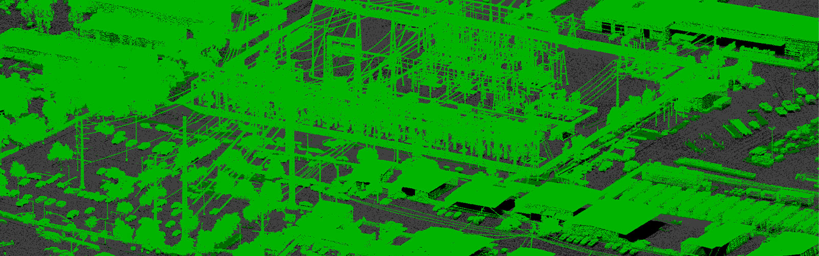
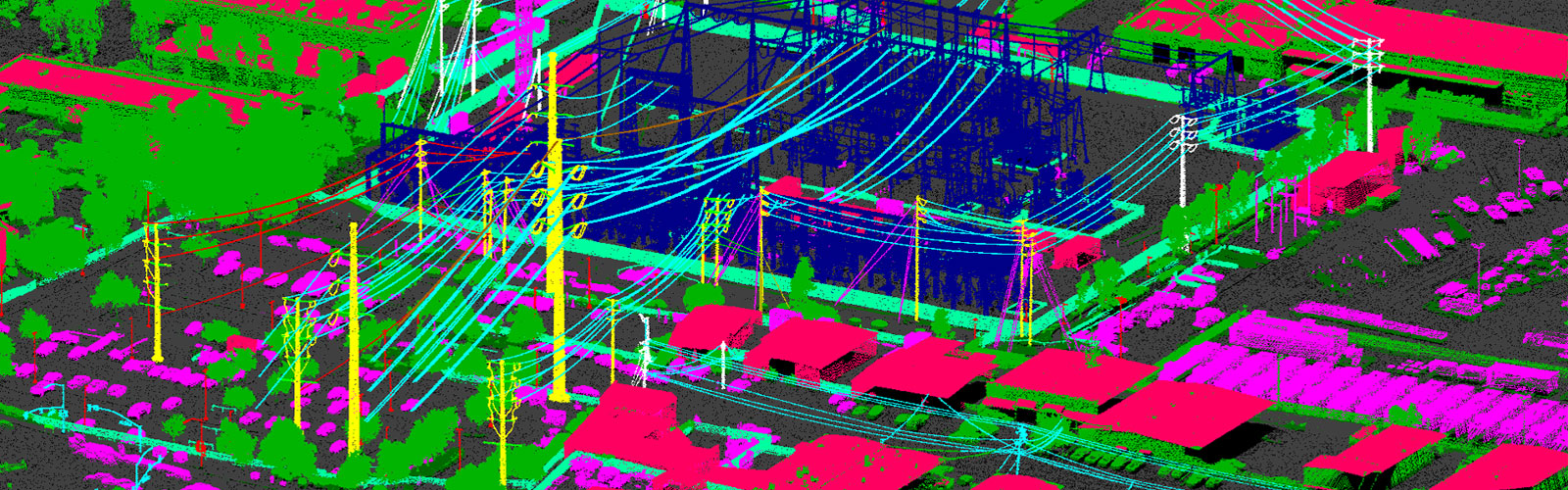
Classification of LiDAR to following classes:
- Ground
- Ground based natural features like Water, swamps and marshy areas, boulders, rocks
- Ground based man-made features: roads, paved and unpaved, driveways, sidewalks, footpaths, trails, parking lots and concrete pads etc.
- Land usages as recreational sites, crop fields, orchids, public facilities etc.
- Overhead features: buildings, raised decks, walls, fences, barriers or guard rails, parking decks, canopies, mail boxes, mile posts, cell towers, lamp posts and various other signs and signals.
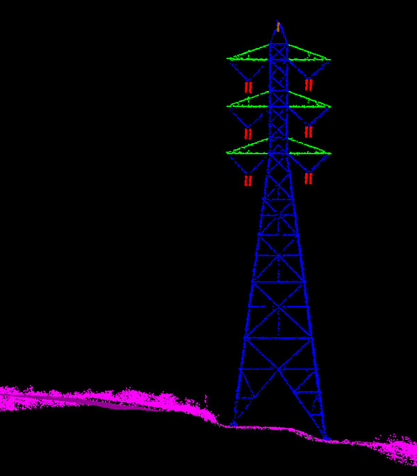
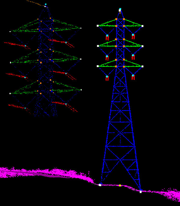
- Powerline infrastructures: Structures including poles and towers, cross arms, conductors including current carrying and current non-carrying wires like shield wires, optical cables and telecom cables attached to powerline structures, transformers attached to poles and substation equipment, guy wires and guy spans, insulators, marker bulbs attached to transmission conductors etc.
- Wires are further classified to subject or mainline, adjacent or other wire that is not subject wire and crossing wire which crosses a subject wire. We also classify the transmission lines circuits to phases as A, B and C or X, Y and Z.
- From vegetation class all returns that are not supposed to be trees or shrubs are moved to an appropriate class.
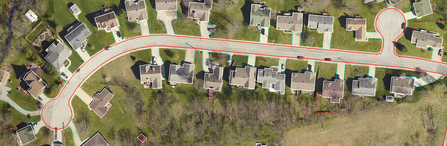
Plamimetric drawing
We prepare a drawing of features with best possible accuracies from reference of point cloud and orthophotos for features listed in the specification of a customer. Few such typical features for which we prepare a planimetric drawing in CAD format are:
- Road features like interstates, highways, street roads, bridges and viaducts
- Rail tracks including the center line
- Sidewalks, driveways, parking lots, unpaved roads and trails
- Buildings excluding decks, ridges of buildings including building corners
- Walls including retaining walls, fences, guard-rails, barriers
- Signs, signals, gantries, lamp posts, flag posts, man-holes, fire hydrants
- Vector for river, streams, creeks, canals, pools, ponds, lakes, swamp.
- Treeline, orchids, landcovers and land uses as recreational site, crop fields, cemetery, junk yard, forest land etc.
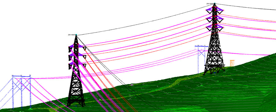
POAs and stringing or drawing 3d catenaries
We place point of attachments for both transmission and distribution lines and string the conductors including the underbuilds.
- Structure bottoms and tops placed at respective centers.
- Attachment points for cross arms
- Points for tower legs at ground
- Attachment points for equipment attached to powerline structures. Points are placed where the equipment is attached to the structure.
- Dead end markers indicating dead end structures.
- Guy wire attachments where the guy wire is connected to the structure and guy anchors where the guy wire enters ground.
- Conductor and shield attachments including 2nd level and third level conductors
- Insulator attachments
- Crossing attachment indicating where wires cross each other.
- Stringing the conductors mostly the subject line matching to the point cloud
- At dead ends conductors are strung to where conductors meet insulators.
Importing LiDAR and POAs to PLS-CADD
After the points are finalized in classification process and edge checked for continuity of features across the plan edge, they are then imported to PLS-CADD to create ".bak" file per circuit. Based upon the feature code file of client LiDAR classes are mapped to the feature codes in PLS class. The POAs are similarly exported out of CAD to text format with appropriate feature codes. Coordinate system and units are set in PLS CADD followed by import of LiDAR and POAs. Planimetric drawing in dxf format and orthophotos for the circuit are attached to it. Finally a backup file is saved with appropriate naming convention as specified in the project specification.